PolyU EIE3128 / EIE3360 - Note (Robot Car) - IoT Workshop and Integrated Projects 2025 (Jan to Apr 2025)
PolyU EIE3128 Info (EEE) (ex code EIE3105)
2024/2025 S2 - IoT Workshop & Integrated Project - Some Note & Info * (Jan 2025)
(Click the photo to enlarge it)
----- ----- * Important Note * ----- -----
1) Please note that each robot car is with a unique number assigned. Please do not exchange the car with your classmates, without approval.
2) Please note that the electric current or the power output of the I/O (Output pin) of microcontroller unit (MCU) STM32F405 is limited. Over electric-current driving will damage the circuit and the I/O pins of the MCU. It might reduce marks. So please make sure to have resistors to limit or protect the I/O pins of the MCU ("+" pin, driven by the output of MCU).
(from https://www.eleccircuit.com/current-limiting-resistor/)
- Some students connect the LEDs and the output pin of the MCU, directly, to drive the LEDs without any resistors to limit the electric current. Some students reported that the I/O pins of their MCU boards were damaged and burnt, because of forgetting to connecting resistors (and running for a long period of time).
- The above diagram shows a good practice with a circuit with a typical 200 ohm to 1k ohm resistor to limit the electric current passing through the LED from batteries or power supply. In your project, the LED could be driven from the I/O pins (outputs) of the MCU and it will damage your MCU without the resistors.
4) Please follow the guideline to assemble your robot car and troubleshoot as instructed.
b) Download Test program(s) c) Download Debug Guidelines
d) Read / Download Line-Tracker IR module Guidelines.
Below is a golden USB dongle with auto-recover-fuse protection: (note: 3.3V TTL should be chosen)


The red one can burn your USB port of the PC and burn your Robot Car when you accidentally make some wrong connections. So please use the golden one instead (with the new connection cable).
** Please note that the old red USB-UART dongle should not be used especially if you experienced MCU burnt. The red USB dongle will be phased out as it doesn't have protection!!!
We are distributing the new golden-color USB-UART dongle (serial adaptor) (which has short-circuit auto-recover / resettable fuse protection) (more than 100 sets purchased).
Technical support will be probably provided in the lab CF005 during lab sessions. The IoT electronic lab (CF005) might be usually open until 18:30.
A photo of an assembled set of robot car: (Bottom Layer)
(Click the photo to enlarge it)
Hardware List
Software List
----- ----- -----
1) STM Microelectronics Cube IDE (STM32CubeIDE)
2) STM32 ST-Link Utility
Tools List
Note to the wirings of the robot car as shown below:
Procedures
Appendix: Module Information
b)
Bluetooth Modules HC-05 / HC-06Bluetooth protocol: Bluetooth Specification v4.0+EDR
Frequency: 2.4GHz ISM band
Operating voltage: 3.3~6V
Transmission speed:
Asynchronous mode: 2.1Mbps (Max) / 160 kbps
Synchronous mode: 1Mbps/1Mbps
HC05 / HC06 Pin connections:
VCC: Connect to 5V (+)
GND: Connect to GND (-)
RXD: Connect to PA2 (HC-05 -> STM32)
TXD: Connect to PA3 (HC-05 -> STM32)
RXD: Connect to D0 (HC-06 -> Arduino UNO)
c) DC Motors
Voltage:
More info:
d) Line Tracker Module
Working voltage: DC3.3V or 5.0V
Output signal: digital signal
Detection distance: 10mm~15mm
Signal status: detect the black line and output low level, detect the white line and output high level, and output low level if it exceeds the detection range
LED status: detect black line LED off, detect white line LED on
Pin connection:
(1) GND: Connect to GND
(2) 5V: Connect to 5V
(3) OUT1: Connect to PB0 (STM32)
(4) OUT2: Connect to PA4 (STM32)
(5) OUT3: Connect to PA5 (STM32)
(6) OUT4: Connect to PA6 (STM32)
(7) OUT5: Connect to PA7 (STM32)
(Line tracker module circuit diagram above - click it to enlarge)
- Please note that the resistors R2, R4, R6, R8, R10 of the new module should use 5100 ohms (mark "512"), instead of 10K ohm (marked "103" on resistor) for a measuring distance of about 1 to 1.5 cm. We have some other line tracking modules with variable resistors. E.g. TCRT5000
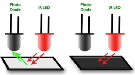
Above diagram shows a basic mechanism of the module. The left one is with a white surface that reflects the light emitted from the IR LED, while the right one does not reflect the light with a black surface.
In the above picture, we are using two IR sensor modules namely the left sensor and the right sensor. When both left and right sensor are sensing white, the robot can move forward.
If the left sensor comes on a black line, the robot can turn the left side, so as to keep the robot car to follow the black line. When both left and right sensor are sensing white, the robot can move forward.
As in the above picture, in case the right sensor is sensing a black line, the robot can then turn right, until both sensors come to the white surface. When they both come to white surface, the robot can start moving on forward again.
When IR light is reflected and received from the sensors, the LEDs will turn ON to indicate that the IR receiving is detected. The corresponding Tera Term output should be “11111”.
When IR light is NOT reflected (or not received) from the sensors, the LEDs will turn OFF to indicate that no IR light is detected. You can also take the robot car, far away from the white surface so that no IR light (reflected) is received (so that the LEDs are off). The corresponding Tera Term output should be “00000”.
e) Speed Counter inside the motor
f) Motor Driver IC DRV8837 (from TI)
g) Sensor Shield Module (from OpenJumper)
Schematics:
h) STM32F405 Development Board Pinouts -
PolyU EEE 2025 (EIE3360 / EIE3128 / EIE3105)
Electrical and Electronic Engineering


Thank for sharing blog read more Best ai tools in 2025
回覆刪除